Thunder IDE Interface - English Version
General
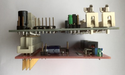
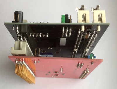
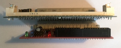
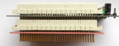
The "Thunder" is an unique interface for the Atari TT, which offers the possibility to connect IDE devices to the Atari TT. It is equal, if you use a hard drive, a CD-ROM or a CF card. Usable master / slave IDE to CF adapter or even IDE to SATA adapter can be used. Even SSD devices now works with the Atari TT. The Thunder is a partial plug and play solution. The extension card is plugged onto the TT-RAM socket of the Atari TT (internal slot in front of the power supply, 96-pin connector). It is only necessary to connect the Thunder with just two cables to the mainboard of the TT.
Features
- new development from the year 2016 (Pakman, Tuxie, Gaga)
- IDE interface for the usage with of 1 or 2 IDE devices (master / slave)
- 100% compatible with the Atari Falcon IDE bus
- currently up to 5.75 MB / s transmission rate (tested with CF card)
- special support from the HDDriver from version 10, with which the driver can be loaded into the Fastram and the transmission rate can be accelerated enormously
- Protection of the TT bus against overload caused by buffered data, address and control lines
- compact design, only 7.1 x 9.9 cm, in SMD construction
- central element is a programmable logic block (CPLD) from Xilinx
- looped TT-RAM socket, which allows an expansion, for example the Storm or other TT Fastram cards
- compatible with other Fastram cards, even with those of Atari
- 3 operating modes selectable via jumper block: Falcon compatible (standard) / ByteSwap (ppera) / SmartSwap (PC an Mac compatible)
- also works in accelerated TT, thus further performance increase (tested with 20MHz bus and 40MHz CPU)
Description
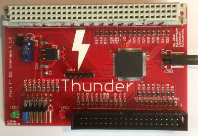
On the Thunder, the 96pin FastRAM socket is looped up and a an coded 40pin standard socket for IDE devices.
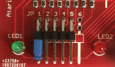
The jumper block JP1 - 6 is also located at the bottom left (see jumper assignment).
The green LED1 signals the operational readiness. The red LED2 signals accesses to the IDE bus.
Con4 in the middle as well as the pins GND and + 5V on the upper left are for programming the CPLD - please leave unused and never connect!
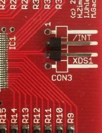
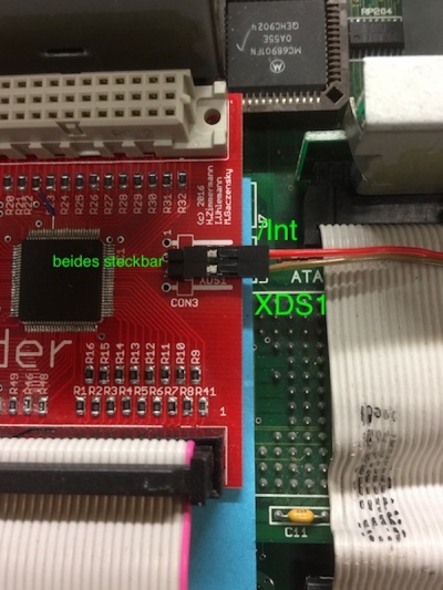
Con3 on the right side connects the two signal lines / Int and XDS1 to the mainboard (see Installation).
On some Thunder there are small hardware patches; please leave so. As of Rev. C, it is also possible to route the LED2 "outwards".
Revisions and Firmware
As of 15th september 2017 there are 4 Hardwarerevisions of the Thunder, namely Rev. A (prototype), Rev. B (= V 1.0), Rev. C and Rev. D. The different revisions have the same features and differ only slightly in the structure, but not in the function.
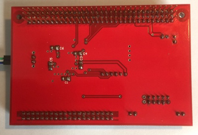
As of 05th august 2017 the actual firmware for all revisions is: 363. This firmware is improved in the timing because there are some very few TT, where this current firmware is needed to work. The firmware used is usually written at the bottom of the Thunder. An update is possible. Thunder with older firmware versions do not need firmware update, if there were so far no problems.
.
Construction and installation
The installation is quite simple:
1.
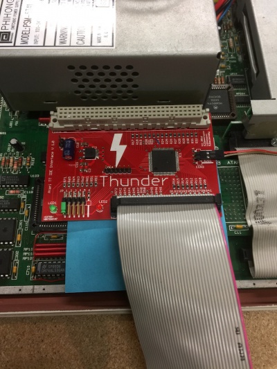
First, insert the Thunder into the TT-RAM slot. Please pay attention to the correct fit! If necessary, the card can also be firmly fixed to the mainboard with two screws. Please insert the card smoothly, evenly and symmetricaly. The Thunder has for this purpose a special 96pin connector with longer, gilded contacts on the bottom, which are for this kind of application (so called gilded transfer zone). With TT's with Daughterboard or PGA CPU it is sensible to isolate the Thunder downwards for safety reasons, in order to avoid short circuits (see pictures below). A separate power supply of the Thunder is not necessary as this is done via the expansion slot.
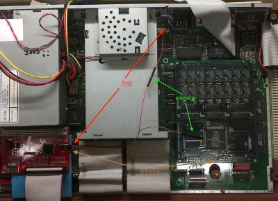
2. Two wired connections (signal lines: /INT and /XDS1) are required to use the Thunder. One end of each cable is plugged into Pin2 and Pin3 of Con3 (right side). Pin 1 and pin 4, which are not used, are ground contacts with which the signal lines can be shielded, but regulary it is not necessarily. In principle, the cables should be kept as short as possible. Genuine, pre-assembled and colored cables are included.
The each other end of the two cables are attached to the following points on the mainboard, best to solder:
- Cable 1 /INT (Pin2 of the Con3 on the Thunder) goes to pin 10 of the DMA connector or to resistor R311 behind the DMA connector (for TT´s with daughterboard or PGA CPU to the right side of R311)
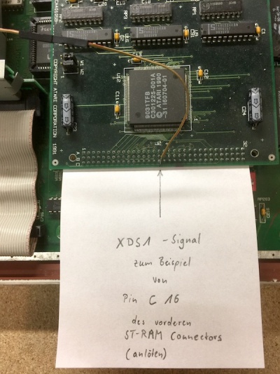
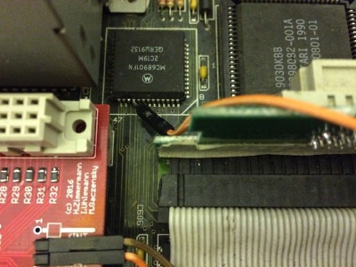
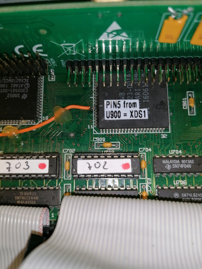
- Cable 2 /XDS1 (Pin 3 of the Con3 on the Thunder) can be soldered to MFP pin 50 or pin 16 of the row C of the ST-Ram card (front connector)
To prevent the /Int and the /XDS1 lines from being interchanged despite the color code, remenber the following crib:
On the Thunder the /Int is the "rear/behind" pin - the signal cable also comes "from behind" on the mainboard. The /XDS1 signal on the Thunder is in "front" - the signal power is also "from the front" on the mainboard.
3. The Thunder is therefore basically ready for use. With an original TOS 3.06 in the TT, because of the peculiarity of this TOS version is only booted from floppy and the IDE extension is put into operation.
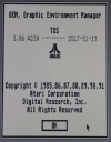
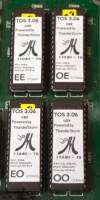
To directly boot from IDE, the TT needs a TOS with the IDE patch. More details can be found in the forum atari-home.de ([1]), along with a reference source. With existing IDE TOS patch a special Thunderstorm logo is displayed at start up and in the desktop under Info you get the following note:
NOTE: The above TOS 3.06 includes the following patches: WinX 2.3n, SHBuffer, BPatch, RamSizeFit, NewLogo, IDE boot. The patched TOS 3.06 is available in following languages: German, English (UK and US), French, Spanish and Swedish.
More is not necessary. A simple test shows whether the card is correctly plugged in and wired: JP1 from the jumper block of the Thunder pull = off = Thunder disabled. The TT should behave the same despite the Thunder, as without the Thunder.
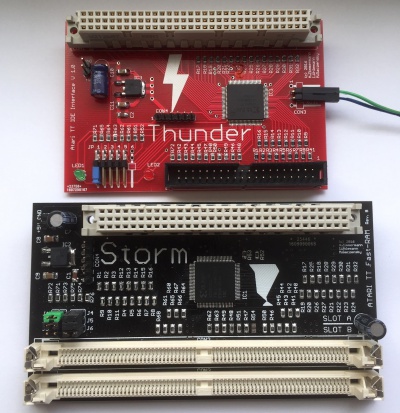
Recommended is the combination with the Storm extension ([2]) to reach the full speed. Especially under Mint, this is clearly noticeable during the installation and the starting process.
.
Configuration, meanings and contexts
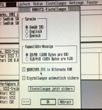
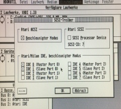
The Thunder was tested with various HDD drivers. The best performance is provided by the Thunder IDE interface, together with the Storm Fastram card, when the hard disk driver is loaded into the Fastram. For the HDDriver version 10 or higher, a feature was introduced under File -> HDDRUTIL settings (HDDRIVER.SYS in Alternate RAM). Furthermore, in the HDDriver (also before version 10) the accelerated mode can be set for IDE devices under Settings -> SCSI driver (Atari / Milan IDE, accelerated mode), which not only offers speed advantages for hard drives but also for CF cards (+ 400 Kbytes / s in accelerated mode).
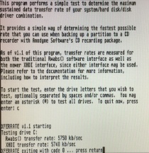
In this case, data transfer rates of up to 5750 Kbyte / s can be reached (test program: Xferrate, compared with Falcon, the transmission rate is only 1400 Kbyte / s).
Note: when using HDDriver, the C: partition must not be set up with byteswap, otherwise from C: can not be booted.
Jumpersettings
- JP1 = IDE Interface: on = Thunder enabled (Falcon compatible mode), off = Thunder disabled
- JP2 = regular or twisted IDE cable: on = twisted (Hardware Byteswap enabled), off = regular (untwisted IDE Cable)
- JP3 = Smartswap on = SmartSwap enabled, off = Smartswap disabled
- JP4 = Speedmode on = Slow Mode, off = Highspeed Mode
- JP5 = Diagnose on = Diagnose enabled, off = Normal
- JP6 = not in use, for futher features
The default setting (bold) is: JP1 on, leave all other jumpers open.
Thunder on (JP1), Falcon compatible standard mode
JP1 turns on the Thunder. JP1 must therefore always be set, also for the other modes. If only JP1 is set, the Thunder is operated in Falcon compliant mode. Data exchange with other non-Atari systems is not possible.
ByteSwap (JP2), Ppera compatible mode
Byteswap is called a mode in which the data lines are twisted (the IDE cable is twisted), this means the lower byte is exchanged with the upper byte during transmission. This technique offers the possibility to read partitions created on the PC without detour on the TT without the CPU having to perform a software byte swap. This saves rendering performance. To use the byteswap mode, however, a special HD driver is required, for example that from ppera.
The Thunder offers this mode under JP2 for users who want to use the ppera driver with a twisted IDE cable.
SmartSwap (JP3), PC/Mac compatible mode
Smartswap is a modified mode of byteswap mode. Here, the bytes are only exchanged when actual data are transferred from the IDE device. All other data needed to control the device is not rotated. Thus no special driver is necessary. HDDriver supports this mode. The partition must be created only Windows compatible.
The Thunder offers this mode under JP3 for users who want to use the HDDriver and want to use the direct data exchange with a Windows computer or Mac.
For this, put JP1 and JP3 on. The data carrier (HDDriver without byteswap!) can easily be exchanged between Atari and PC / Mac, ideal for CF cards.
Slow Mode (JP4)
The Slow Mode is a mode that is used with quite old IDE devices. The Slow Mode is only installed for better compatibility and will not be used with newer devices. In case of problems the setting of JP4 can help. Recommended setting: off.
relationships
- JP2 = off and JP3 = off: standard, such as Falcon IDE interface
- JP2 = off and JP3 = on: SmartSwap such as Suska, it means Data bytes are scrambled, except IDENTIFY DEVICE
- JP2 = on and JP3 = no matter: Twisted, it means replace the data lines according to the proposal of ppera
.
Pictures of the installtion
For more infos see here [3].
Thunder installed with isolation downwards to the CPU daughterboard.
Installation of the /Int signal line in a TT with daughterboard or PGA-CPU (CPU front left in the area before the power supply / under the Thunder)
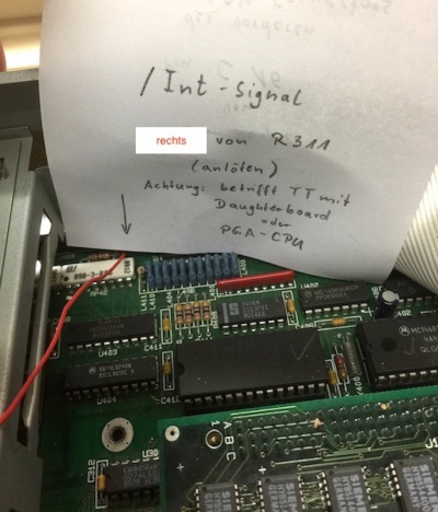 ---->
----> 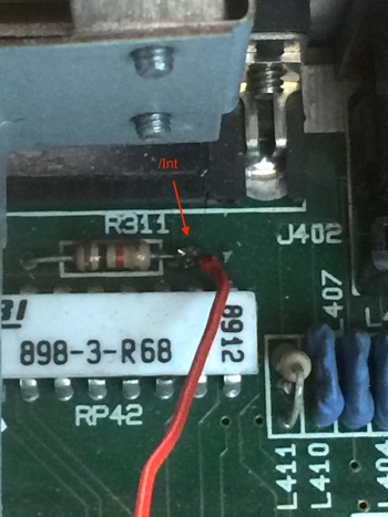 solder it the right side of R311
Installation in a TT with soldered QFP CPU (approximately in the middle of the mainboard)
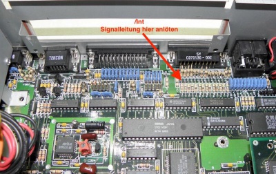 ---->
----> 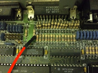 solder it rear of the R311
Installation of the /XDS1 signal line (applies to all TTs)
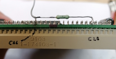
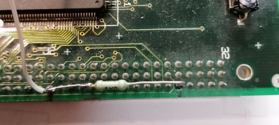
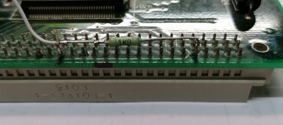
optional: with a 1K Ohm resistor between Pin C16 und C28 of the front ST-RAM connector you can improve the signal quality of XDS1
alternative installation of the XDS1 signal line
you can solder it at Pin 50 in TTs with soldered PLCC MC68901
or you can solder it at Pin 5 of U900
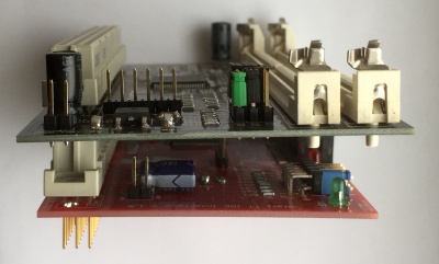
Thunder and Storm in combination
For more infos and Pictures see [4]
.
Revisions and tested adapters
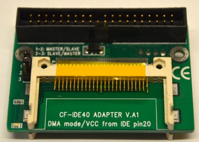
 left: IDE to Dual CF (Master/Slave),
right: IDE to SATA
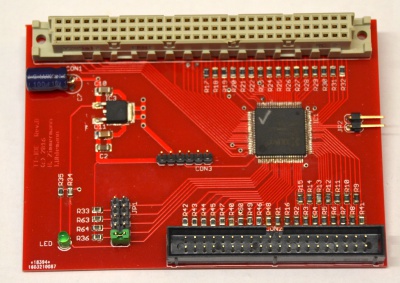
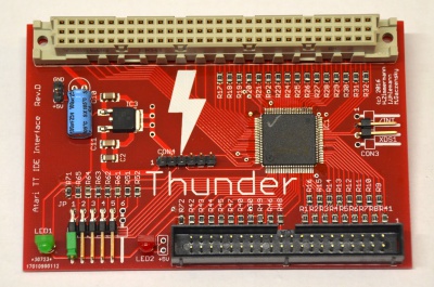 left: Prototyp,
right: actual Revision D
last update from 21. April 2021 (Gaga & Tuxie)
