Nicht kategorisierte Dateien
Aus Atari Wiki-NEU
Zur Navigation springenZur Suche springenUnten werden bis zu 100 Ergebnisse im Bereich 101 bis 200 angezeigt.
Zeige (vorherige 100 | nächste 100) (20 | 50 | 100 | 250 | 500)
 26RhothronKatalog.jpg 1.280 × 960; 406 KB
 27RhothronKatalog.jpg 1.280 × 960; 445 KB
 28RhothronKatalog.jpg 1.280 × 960; 388 KB
 29RhothronKatalog.jpg 1.280 × 960; 410 KB
 2RhothronKatalog.jpg 1.280 × 960; 401 KB
 2Soundp.jpg 800 × 600; 175 KB
 3.et4000.jpg 1.024 × 768; 361 KB
 30RhothronKatalog.jpg 1.280 × 960; 407 KB
 31RhothronKatalog.jpg 1.280 × 960; 380 KB
 32RhothronKatalog.jpg 1.280 × 960; 376 KB
 33RhothronKatalog.jpg 1.280 × 960; 393 KB
 34RhothronKatalog.jpg 1.280 × 960; 313 KB
 3RhothronKatalog.jpg 1.280 × 960; 436 KB
 3Soundp.jpg 800 × 600; 248 KB
 4.et4000.jpg 1.024 × 768; 421 KB
 4Kanal AD WandlerBS.jpg 1.024 × 768; 398 KB
 4RhothronKatalog.jpg 1.280 × 960; 386 KB
 4Soundp.jpg 800 × 600; 251 KB
 5.et4000.jpg 1.024 × 768; 387 KB
 5750.jpg 1.050 × 1.080; 560 KB
 5RhothronKatalog.jpg 1.280 × 960; 472 KB
 6.et4000.jpg 1.024 × 768; 400 KB
 68k-Mega-Bus-Adapter.jpg 1.226 × 374; 60 KB
 6RhothronKatalog.jpg 1.280 × 960; 437 KB
 7.et4000.jpg 1.024 × 768; 339 KB
 7RhothronKatalog.jpg 1.280 × 960; 375 KB
 8.et4000.jpg 1.024 × 768; 426 KB
 8RhothronKatalog.jpg 1.280 × 960; 470 KB
 9.et4000.jpg 1.024 × 768; 380 KB
 9RhothronKatalog.jpg 1.280 × 960; 502 KB
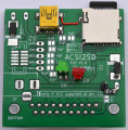 ACSI2SD EXT V1 BOTTOM.JPG 2.800 × 2.856; 3,35 MB
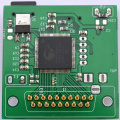 ACSI2SD EXT V1 TOP.JPG 2.804 × 2.806; 3,57 MB
 AGVGA2BSkl.jpg 500 × 279; 34 KB
 AGVGA2lskl.jpg 500 × 285; 34 KB
 ASO1.jpg 600 × 800; 188 KB
 ASO10.jpg 800 × 600; 184 KB
 ASO3.jpg 800 × 600; 207 KB
 ASO4.jpg 800 × 600; 194 KB
 ASO5.jpg 800 × 600; 164 KB
 ASO6.jpg 800 × 600; 154 KB
 ASO7.jpg 800 × 600; 153 KB
 ASO8.jpg 800 × 600; 189 KB
 ASO9.jpg 800 × 600; 188 KB
 ATOS-Card1a.jpg 1.200 × 1.567; 269 KB
 AT Speed Platine von Sack.jpg 1.024 × 768; 424 KB
 AT Speed Platine von Sack Rueckseite.jpg 1.024 × 768; 336 KB
 Abb01 Daughterboard Speedy 0v2.JPG 4.032 × 3.024; 2,81 MB
 Abb01 Daughterboard Speedy 1v0.JPG 2.015 × 1.545; 1,88 MB
 Abb01a Daughterboard Speedy 1v0 bottom.JPG 1.920 × 1.458; 2,19 MB
 Abb02 PGA-Speedy 0v2.jpeg 1.280 × 960; 509 KB
 Abb02 PGA-Speedy 1v0.JPG 1.920 × 1.199; 1,37 MB
 Abb02a PGA Speedy 1v0 bottom.JPG 1.920 × 1.272; 1,2 MB
 Abb03 SMD-Speedy 0v2.JPG 3.024 × 4.032; 3,32 MB
 Abb03 SMD-Speedy 1v0.JPG 1.920 × 1.345; 1,73 MB
 Abb03a SMD Speedy 1v0 bottom.JPG 1.920 × 1.272; 1,58 MB
 Abb03b SMD Speedy with the sockets plugged in from below.JPG 1.920 × 1.272; 1,37 MB
 Abb04 Mainboard SMD-TT with marked IC.JPG 1.440 × 1.920; 933 KB
 Abb05a six new sockets for SMD Speedy.JPG 2.558 × 2.195; 3,31 MB
 Abb06 Third type of patch.JPG 1.903 × 540; 854 KB
 Abb06b Fourth type of patch.JPG 1.920 × 1.440; 920 KB
 Abb07a CPU place of SMD TT with divided BG signal.JPG 3.024 × 4.032; 2,29 MB
 Abb07a CPU place of SMD TT with divided BG signal.jpg 1.920 × 1.276; 555 KB
 Abb07b CPU place of SMD TT with divided BG signal.JPG 1.920 × 1.272; 1,63 MB
 Abb07b CPU place of SMD TT with divided BG signal.jpg 2.357 × 1.567; 809 KB
 Abb07c CPU place of SMD TT with divided BG signal.JPG 1.920 × 1.272; 1,58 MB
 Abb07d CPU place of SMD TT with divided BG signal.JPG 3.024 × 4.032; 2,85 MB
 Abb08 Speedy with female socket under PCB.JPG 1.920 × 1.272; 1,42 MB
 Abb09a SMD TT with all changes ready to install SMD Speedy.JPG 3.024 × 4.032; 2,93 MB
 Abb10a SMD TT with SMDSpeedy.JPG 3.024 × 4.032; 3,04 MB
 Abb10b SMD TT with SMDSpeedy.JPG 4.032 × 3.024; 2,57 MB
 Abb11a PGA Speedy Pin closeup.JPG 1.920 × 1.440; 712 KB
 Abb11a PGA TT state machine.jpg 1.920 × 1.080; 879 KB
 Abb11a SMD Speedy insert.JPG 1.920 × 1.272; 1,44 MB
 Abb11b PGA TT state machine entfernt und gesockelt.jpg 4.054 × 2.829; 1,74 MB
 Abb11b SMD Speedy inserted.JPG 1.920 × 1.272; 1,49 MB
 Abb11c SMD Sppedy with Storm TT RevG.JPG 1.920 × 1.272; 1,79 MB
 Abb12 Daughterboard TT Mainboard with new Daughterboard Speedy.JPG 3.024 × 4.032; 3,37 MB
 Abb12a CPU of PGA TT with divided BG signal.jpeg 1.619 × 1.920; 955 KB
 Abb12b CPU of PGA TT with divided BG signal.jpeg 1.080 × 1.920; 406 KB
 Abb12c CPU of PGA TT with divided BG signal.jpeg 1.080 × 1.920; 579 KB
 Abb12d CPU of PGA TT with divided BG signal.jpeg 1.920 × 1.440; 1.019 KB
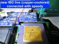 Abb13 BG line to PGA Speedy.JPG 1.920 × 1.440; 758 KB
 Abb14 Cable between R61 and U701 Pin1.JPG 4.000 × 3.000; 3,17 MB
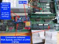 Abb14a PGA Speedy with conntection to Pin1 from U704.JPG 1.920 × 1.440; 986 KB
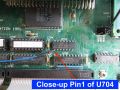 Abb14b PGA Speedy Pin1 of U704.JPG 1.920 × 1.440; 984 KB
 Abb15 PGA-TT Mainboard with all changes.JPG 1.920 × 1.440; 931 KB
 Abb16 Mainboard DB TT with marked Daughterboard.JPG 1.920 × 1.440; 762 KB
 Abb17a DB-TT Co-Pro-Patch 01 mod.JPG 4.032 × 3.024; 2,97 MB
 Abb17b DB-TT Co-Pro-Patch 02 mod.JPG 4.032 × 3.024; 2,46 MB
 Abb18 DB-TT Co-Pro-Patch 04.JPG 1.440 × 1.920; 857 KB
 Abb19 Daughterboard TT Mainboard with new Daughterboard Speedy.JPG 1.920 × 1.272; 1,75 MB
 Abb20a extra VG96.JPG 1.920 × 1.272; 1,58 MB
 Abb20a perfekter Komplettaufbau.JPG 1.920 × 1.272; 1,16 MB
 Abb20b RAM.jpg 1.732 × 1.920; 950 KB
 Abb20c DB Speedy mit modifizierter Lightning.JPG 1.920 × 1.272; 1,35 MB
 AdvantagePlus1.jpg 1.280 × 960; 519 KB
 AdvantagePlus2.jpg 1.280 × 960; 604 KB
 AdvantagePlus3.jpg 1.280 × 960; 421 KB
 Afterburner040.jpg 1.424 × 1.068; 422 KB
 Ambox content.png 40 × 40; 3 KB


Zeige (vorherige 100 | nächste 100) (20 | 50 | 100 | 250 | 500)