Cloudy
Overview
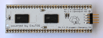
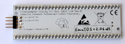
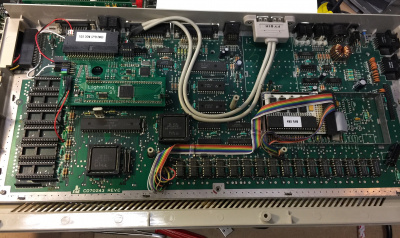
The CLOUDY is an extremely compact TOS adapter to be used together with the Lightning ST (at least with firmware version mx02_rp) and/or with the Storm ST in every ATARI ST, STM, STF, STFM or MegaST.
It allows you to switch between two TOS ROMs: one ROM comes with EmuTOS 0.9.12 preinstalled, the other one can be flashed via software by you, for example with TOS 2.06. See below for an important note about supported TOS versions.
Care has been taken to make the installation as easy as possible: The Cloudy can be soldered directly on top of the CPU. It has the same dimensions like the DIL socket that is otherwise required to install the Lightning ST. In that way, Cloudy and Lightning ST will fit even into the little space available on some STs. If you prefer, the Cloudy will also work on top of the Lightning ST, though.
Only two jumper wires need to be connected to the Lightning ST for the Cloudy to work – plus two extra wires to a switch in case you want to switch between the two possible TOS/EmuTOS versions.
Please note: to use Cloudy, you need an adress decoder (hexE00000) . The matching adress decoder is offered by the Lightning ST, alternatively by the Storm ST.
In a nutshell:
- Works in every ST (together with the Lightning ST and/or the Storm ST)
- Extremely compact
- Comes with EmuTOS preinstalled
- A second operating system can be flashed
- Flash software is provided
Supported TOS versions:
- TOS 2.06, EmuTOS 256k ROMs: always!
- TOS 1.00 – 1.04, KAOS 192k ROMs: only if your STs mainboard supports 1 Mbit ROMs. This is the case if your mainboard is currently fitted with only two TOS ROMs. Also, many mainboards with six ROMs can also be re-configured for 1 Mbit ROMs. Inquire with us if you plan to use TOS 1.0x in the Cloudy and are unsure about the capabilities of your board.
Installation of Cloudy
Important note: Please use the connectors (64pin) as rare as possible, as they are not designed for multiple in and out. They can be borrowed and cause contact problems. An intermediate socket or the >cautious< bending of the pins to be inserted can be a remedy.
Variant 1 - Installing Cloudy into a CPU socket:
- In case the mainboard of your ST has a socket for the CPU, the Cloudy can be placed into that socket.
- Be sure that the “<” marking on the Cloudy and the corresponding marking on the mainboard and/or socket are on the same side.
- Then carefully push the Cloudy into the socket.
- Continue with the section “wiring” below.
- Variant 1 is suitable for all 520ST and MegaST, as there is enough space up inside the case. Variant 1 is not suitable for the 1040ST because of the limited space due to the keyboard above.
Variant 2 - Soldering the Cloudy on top of the CPU:
- Variant 2 is suitable for 1040ST, because the Cloudy directly on the CPU is also the socket for the Lighnting ST. This even fits under the keyboard into the original case.
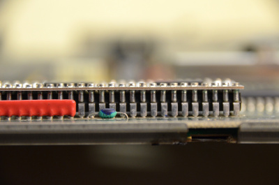
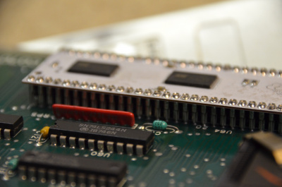
- As shown in the photo in the following section, shorten 32 pins on one side of the Cloudy using a small wire cutter. This allows you to place the Cloudy directly on top of the 68000 CPU.
- Be sure that the notch on the CPU and the “<” marking on the Cloudy are on the same side and that all pins are aligned.
- Temporarily install the provided DIL64 socket on top of the Cloudy. This will ensure that the pins of the Cloudy will remain fixed during soldering.
- Solder all 64 pins of the Cloudy to the respective pins on the CPU.
- Afterwards check that there is no solder bridge between adjacent pins.
- You can now remove the DIL64 socket again.
Wiring:
- Use two jumper cables to connect Cloudy and Lightning ST:
- Cloudy P1 => Lightning ST P11
- Cloudy P2 => Lightning ST P12.
- If you want to be able to easily switch between the TOS ROMs on the Cloudy board, wire a switch (SPST) between Cloudy P3 and P4. Otherwise you can use the provided jumper.
Lightning ST:
- Push the Lightning ST into the sockets of the Cloudy, again making sure that everything is correctly aligned.
- Continue with the Lightning ST installation as described in its separate README or here.
- In particular the ROM2 connection from the mainboard to the Lightning ST is required for the Cloudy to function!
Installation pictures
Important note: Perform all work without electricity!
Disconnect all external wires and open your ST. Loosen all screws on the underside.
Remember that this will void your warranty!
1040ST
Remove the top shell.
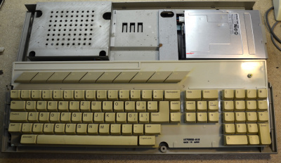
Then remove the keyboard.
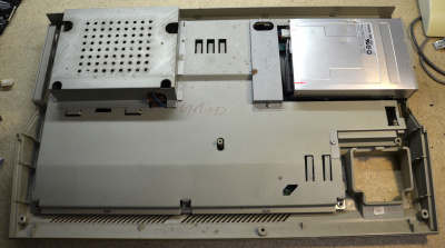
Carefully remove the power supply and the shielding plates. Its helpfull to remove the floppy drive and the lower shell.
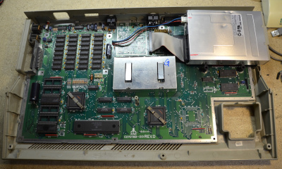
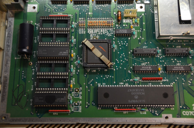
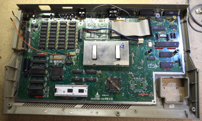
This is the interesting area of a 1040ST: The CPU is located at the front underneath the keyboard. On the left are the original ROM ICs.
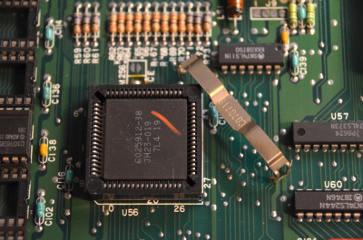
Now is the right time to remove any remaining metal clamps from the PLCC socket U56 (MMU). This will avoid short circuits to the Lightning ST, which will be assembled above later. The clamp is no longer required.
Variant 1: Solder a socket directly to the CPU. Make sure that the solder joints are in order and do not form a short circuit. Pay attention to the notch for the correct alignment (here right). On the example pictures the pins 1-4 of the Cloudy must point to the left in the direction of the ROM sockets.
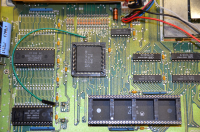
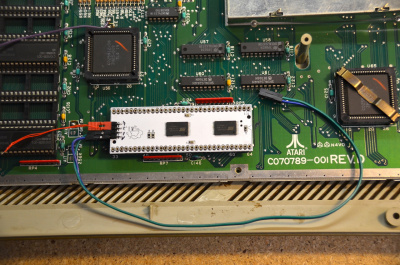
A green jumper cable for the Lightning ST has already been soldered to the tap of the ROM2 signal on the mainboard.
Variant 2: The Cloudy serves as a socket für the Lightning ST. For this it has to be placed directly on the CPU.
Thermal problems of the CPU are not to be expected.
To bring the Cloudy as close as possible to the CPU, remove the thinner ends from one of the two 32 pin rows and carefully remove any burrs if possible.
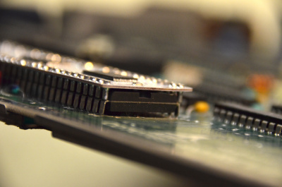
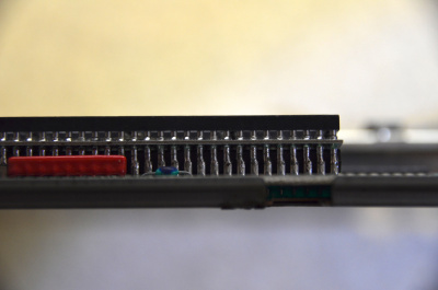
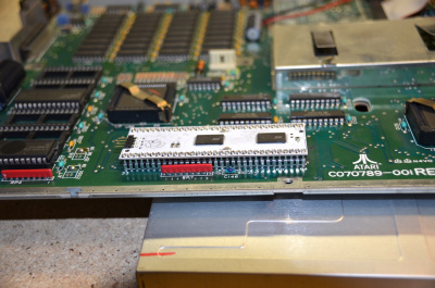
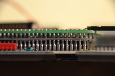
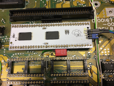
Here you see what I mean: the shortened pins of the Cloudy stand on top of the pins of the CPU. This is how it should look before soldering.
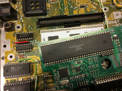
Take a look at the picture on the right, because it clearly shows how close the Lightning is to the CPU.
Please pay attention to the correct alignment before it is too late!
Note: We strongly recommend to assemble an 68000 socket on top of the Cloudy before soldering. This will keep the Cloudy Pins properly aligned during the soldering process. Once soldering is finished, the 68000 socket can be removed.
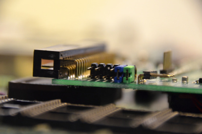
Left Pic: Front view. Right Pic: Rear view. Here you can also see that the pins in this row are not shortened. But you can also shorten this pin row before soldering if you like.
Total view. If you've come this far, you've done most of it. By the way, the Atari should work in this state exactly as before (with the old TOS). You can test it here if you want.
Now it's time for the wiring.
On the left you see the 4 pins of the Cloudy with the inscription 1-4 upside down.
- Take two different coloured jumper cables and plug them to pin 1 and pin 2. Later you see the cable from pin 1 to pin 11 of the Lightning ST and the cable from pin 2 to pin 12.
- You also see a red jumper on pins 1 and 2 of the Cloudy. The jumper has a loose loop to pull it off later. Remember: when this red jumper is plugged in, the Cloudy runs with the emergency OS, an EmuTOS 0.9.12. Of course you can work with this OS, but you can't overwrite it. If you'd rather use the rewritable OS right away, then remove jumper 1-2 now.
The Cloudy is ready with it. The next step is to uninstall the old TOS from the mainboard and install the Lighnting ST.
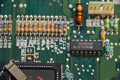
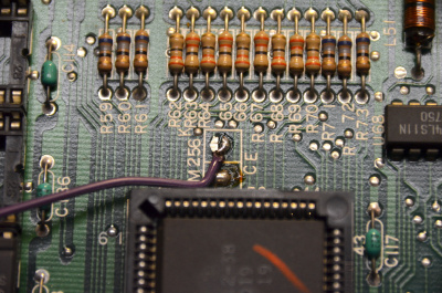
Locate this location to pick up the necessary ROM2 signal from the motherboard. The spot looks like a tin blob or two opposing crescents and is labeled CE.
On the example picture it is located above the MMU between ROM socket. Solder a 10cm long cable (here purple) to the right crescent or to the solder bead 1M. The other end of the cable has a socket, which goes later to R2 of the Lighting ST.
Nearby there should be a 14pin 74LS11. If not, refer to the remarks on the bottom of this page.
Please take care to provide good power supply (VCC and GND) to the Lightning ST, since USB devices might be powered via the Lightning. To do this, take +5V and Ground off the mainboard at a suitable place and lead it with 2 long jumper cables (here red and black) to the corresponding connection of the Lighnting.
If you want to use the IDE part of the Lighnting ST, solder a jumper cable for the INT signal (grey here) to pin 10 of the internal DMA connector (always the right outer pin). The other end comes later to the INT connector of the Lightning ST. Some hard disk drivers require the INT signal for evaluation.
Now lever the original ROM IC out of the socket. You should write them with HI and LO if you want to use them again later. However, this won't be necessary with the Cloudy, because you can also flash this TOS with an image on the Cloudy if you like. So you are always compatible, for example with games. The preparation of the Cloudy and the mainboard is now finished. Yeah!
Now comes the simple part: Put Lighnting ST on the Cloudy and plug in the cables.
- First position the Lightning ST over the Cloudy. Pay attention to the correct alignment of the Lighnting ST on the basis of the marking in comparison to the Cloudy/CPU!
- Then press the Lightning ST carefully and evenly onto the Cloudy.
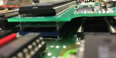
- On the left you can see it correctly: below is the mainboard with the black CPU, then comes the Cloudy (white) and above it the Lightning ST (green).
Note: before plugging in look at the inscription of the pins of the Lighnting ST on the printed back.
Since I'm almost sure you forgot to look at the back of the Lighnting ST, here's a picture. Of interest are the pins R2 and INT.
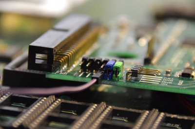
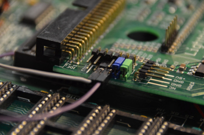
On the left is the corresponding connection of the Lighnting ST on the upper side. Now orient yourself best to the missing pin. The blue and the green jumper set the operating mode of the IDE port. Leave these jumpers as they are (here Smartswap).
Now connect the Lighnting ST as follows:
- First the ROM2 signal from the mainboard (here green) to R2 of the Lighnting ST.
- Then the INT signal from Pin10 of the DMA connector (here grey) to INT of the Lighnting ST.
- Next the two cables of the Cloudy: Pin1 of the Cloudy to Pin11 of the Lighnting ST and Pin2 of the Cloudy to Pin12 of the Lightning ST.
- Finally 5V and ground to the Lightning power connector.
This is how the wiring should look like.
Congratulations, it's done!
If you assemble the computer now, it should report with an OS of the Cloudy. If not, check everything again exactly. If it still doesn't work, contact me.
How to use the IDE part and/or the USB part of the Lightning ST you can read the readme.txt in the folder Info on the Lightning ST diskette or here[[1]].
520ST
The 520ST in the shown mainboard revision (without internal floppy, here even without TV modulator) has the advantage that there is quite a lot of space.
The installation of the Lighnting ST is very easy. Only a standing capacitor near the CPU should be tilted a bit.
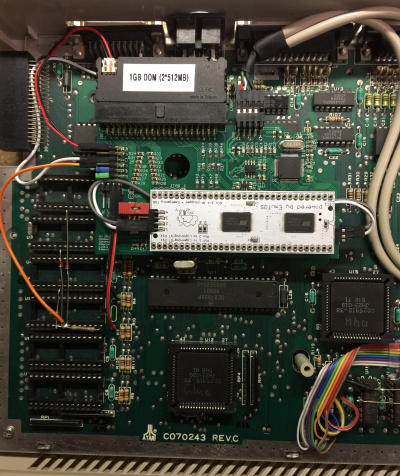
Here you can see a 520ST (without a 74LS11 and no ROMs installed) with a Lighnting ST, which sits in a socket soldered on the CPU.
You can see impressively how well a Disk on Module fits into the IDE port and how the USB bracket can be cleverly moved to the back.
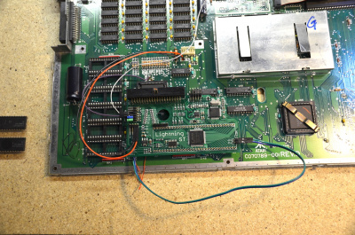
Here the Cloudy with the DualFlash OS is set and wired to the Lightning ST. The original six ROM IC have to be removed.
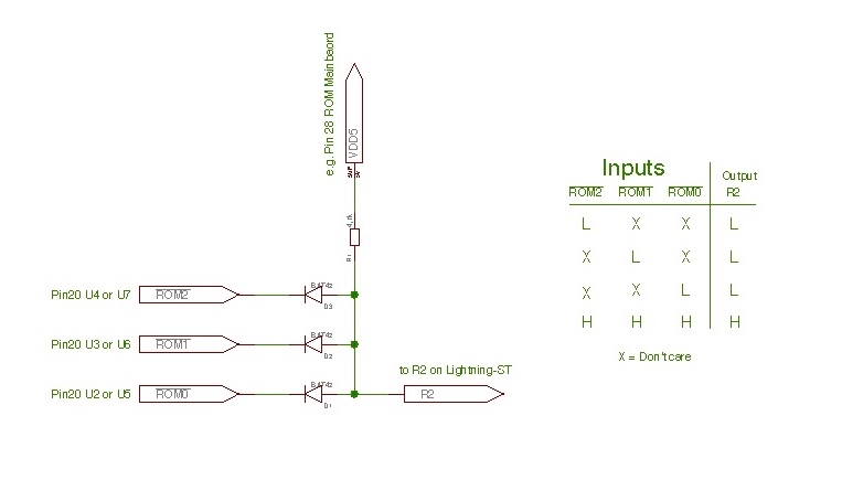
Note the generation of the R2 signal by three diodes and a resistor (see below in the text).
MegaST
The installation inside of a MegaST is quit easy because the space is not limited. If your processor is not socket, please have a look to the section above "Variant 2 - Soldering the Cloudy on top of the CPU". In any case it is useful to put the Cloudy under the Lightning-ST in case of two reason.
- Reason 1: In that way the Lightning-ST has always a socket. You can remove the Lightning-ST if it's nescessary.
- Reason 2: You need a little more space to place the Lightning above the ROM sockets of the mainboard.
The following pictures show a mainboard with a socket.
MegaST with Cloudy
Placing Lightning-ST top of Cloudy.
Picture show the sandwich of Cloudy and Lightning-ST
Flashing the Cloudy
Cloudy comes with the capacity to store two TOS versions.
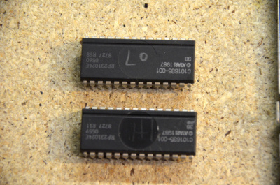
Supported TOS versions are EmuTOS 256k, Atari TOS 1.00 – 1.04 (and derivatives thereof, e.g. KAOS) and Atari TOS 2.06.
Note about TOS 1.0x support:
For the Cloudy to be able to support TOS 1.00 – 1.04, your ST mainboard needs to be able to run from a set of two ROMs. If your ST currently uses six (not two) TOS ROMs, many mainboards can be reconfigured for two ROMs, making it possible to use TOS 1.0x in the Cloudy. Often, to configure the mainboard for two ROMs just three solder bridges on the mainboard have to be changed from the setting marked “256k” to the setting “1M”. However, the exact steps depend on the mainboard revision.
We intend to provide links to reconfiguration guides for common mainboard revisions in our Wiki. Until then, if you’re unsure, please feel free to ask us. Please provide the exact mainboard type (Cxxxxxx, Rev. X). Be aware that EmuTOS 256k and TOS 2.06 are always supported, regardless of mainboard type and configuration.
Cloudy slot 1;
Jumper set between P3/P4 or switch closed: EmuTOS.
EmuTOS is a free operating system that features functionality similar to TOS. EmuTOS is free Software, so it is better than TOS in several ways: It is improved, to support more features and more hardware than Atari TOS. For example, it already includes a hard disk driver that supports the IDE port of the Lightning ST. Furthermore, EmuTOS is actively developed and supported: https://emutos.sourceforge.io/. While EmuTOS in slot 1 also serves as a recovery OS (in case the OS in slot 2 is unable to boot), we encourage you not see it merely as a backup solution but as the fully featured OS which it is.
Cloudy slot 2;
Jumper removed between P3/P4 or switch open: User flashable (but also programmed with EmuTOS at delivery).
This slot can be flashed by you with any of the supported TOS versions (see above). The necessary software FLASHROM.TTP is provided.
To flash a new TOS image:
- Boot into slot 2 (jumper removed/switch open).
- When starting FLASHROM.TTP, the Desktop will ask you to enter the file name of the TOS image. On most TOS versions, you can also simply drag and drop the icon of the TOS image file onto the icon of FLASHROM.TTP.
- FLASHROM.TTP will ask you once for confirmation by pressing “Y”.
- Then it will flash the provided TOS image into slot 2. It is normal for the screen to flicker during flashing.
- Afterwards your ST will reboot into the newly flashed TOS.
- Have fun!
Recovery
In case your TOS in slot 2 does not work, e.g. after flashing a corrupted TOS image:
- Boot into EmuTOS in slot 1 (jumper 3-4 set/switch closed).
- Run FLASHROM.TTP as described above. It will automatically detect that it is running in recovery mode and will ask you to remove the jumper (or flip the switch) while the computer is on.
- FLASHROM.TTP will then re-flash slot 2 and will afterwards boot into the newly flashed TOS in slot 2.
Slot 1 will never be overwritten and can therefore always be used for recovery when needed.
Note: The jumper on the Cloudy might be hard to reach since it is located underneath the Lightning ST. You might want to tie a small piece of yarn around the jumper to use it as a strap for pulling the jumper when FLASHROM.TTP tells you to do so.
You can get the FLASHROM.TTP from the download section of newtosworld[[2]].
Additional notes and hints
Matrix of combination of CLOUDY and LIGHTNING-ST Rev.B:
Explanation:
X   - Don't care
1  - Jumper is set
0  - Jumper is not set
U   - depent on user
-   - not use or remove
1-2 - Jumper is set to position 1-2
2-3 - Jumper is set to position 2-3
CL1 - Pin 1 on CLOUDY
CL2 - Pin 2 on CLOUDY
L11 - Pin 11 on Lightning-ST Rev.B
L12 - Pin 12 on Lightning-ST Rev.B
Li  - Pin marked on Lightning ST Rev.B with R2
TOS-FC - TOS on adress FC0000, e.g. TOS-1.00, TOS-1.04 or KAOS
TOS-E0 - TOS on adress E00000, e.g. TOS-2.06 or emuTOS
Remarks:
- The initial mode of CLOUDY requires the mainboard TOS running at adress range FC0000.
The TOS version itself (TOS 1.00, 1.02, 1.04, KAOS, EmuTOS etc.) does not matter, all of them work fine. Running a mainboard TOS at E00000 (TOS 2.06) would disturb the flashing operation, so it won't work.
- For the initial flash mode it does not matter whether the flashed TOS will finally work at E00000 or FC0000. Flashing is always happening at the address range E00000 anyhow.
Depending on the TOS version you are intending to use with Cloudy there are basically 3 scenarios:
1. Flashed TOS will run at E00000
- Lightning ST will do the address decoding completely on its own
- Will work fine, no more things to consider
2. Flashed TOS will run at FC0000, mainboard was using 2x ROMs before
- Lightning ST will rely on the address decoding already available on the mainboard
- If the mainboard was using 2x 1MBit ROMs before, then it is already set up properly
- Will work fine, no more things to consider
3. Flashed TOS will run at FC0000, mainboard was using 6x ROMs before
- Lightning ST will rely on the address decoding already available on the mainboard
- Some mainboards are prepared to use 2x ROMs as well, featuring a 74LS11 and 3 jumper locations. This applies to all Mega-ST models as well as some 1040ST models. If so, just switch to the 2x ROM setting, and you are done.
- If your mainboard does not have that feature, there is still a way: Adding and wiring a 74LS11 like at the Mega-ST, or combining the 3 CS signals (ROM2, ROM1 and ROM0) from the GLUE with 3 diodes.
- If you use a PAK030 inside of your ST, you can also flash and/or use the Flash at CLOUDY! Please set Jumper 7 on PAK at position 2-3 to disable the TOS on PAK.
- The two slots of Flash could be used as normal flash (slot 2), and fallback flash (slot 1). This is helpful for recovery in case the flashed TOS has malfunction.
- If you would like to switch the TOS versions frequently (for example for testing software) we recommend to use a switch instead of a jumper. Please make sure that you are NOT switching while TOS is running.. most likely it will crash. (Anyhow, it is fine to switch while power is on, but with the reset button pressed).
Using 74LS11
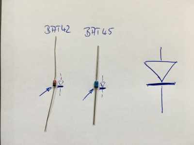
If you need a 74LS11 to stick the three signals /ROM2, /ROM1 and /ROM0 of the mainboard together, here is a other possibility to stick these signals together. You need three Diodes and a resistor. It is useful to take Schottky diodes because the state of high and low could be better interpret from your computer. Useful diodes are BAT42 or BAT45. The resistor should be 4,7 k-Ohm.
Circuit and logic
Please be attention to the direction of diodes. The cathode is the big black stripe and must be placed to the signals /ROM2, /ROM1 and /ROM0!
The picture above show the marking of cathode on the diodes and in schematic.
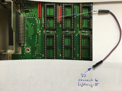
This 1040ST (without a 74LS11) show the patch with three BAT45 and the resistor.
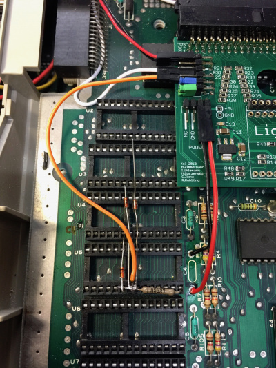
This 520ST (without a 74LS11) show the patch with three BAT42 and a 4,9 kOhm resistor. The orange cable brings the R2 signal to the Lighnting ST.
07.01.2020, gaga
17.12.2019, pakman
17.12.2019, R^2
